


EREMA® (ELECTRIC RESISTANCE MATERIAL)
[ Silicon Carbide Heating Element ] Registered United States Patent and Trademark Office
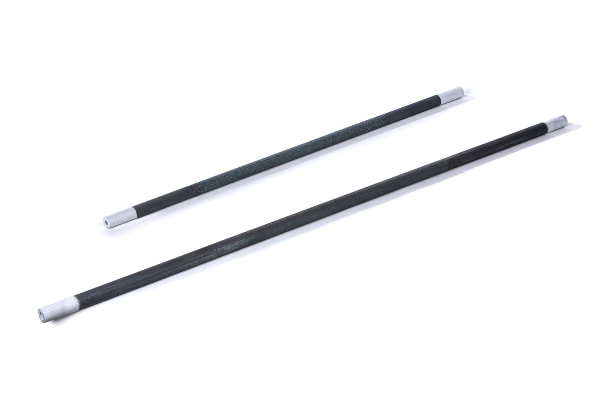
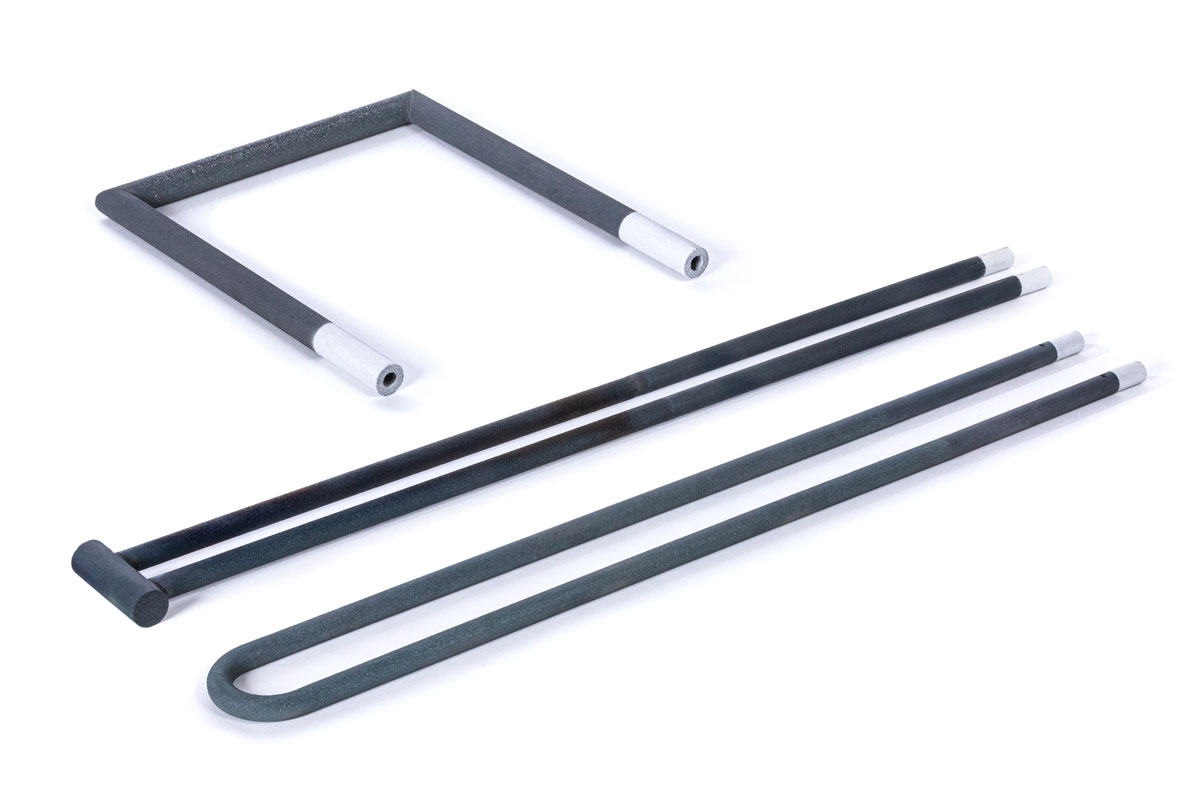
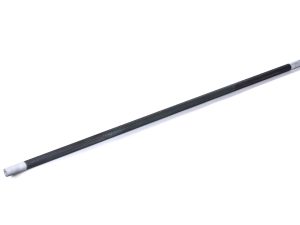
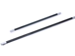
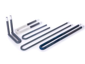
Composed of high-purity silicon carbide (SiC), EREMA heating elements are the first silicon carbide heating elements marketed in Japan. Since we made them commercially available in 1927, we have been committed to research based on our wealth of experience, striving to improve their quality using our unique development technologies and other internal and external technologies. Now, we have been highly regarded for our production scale, which is the largest in the industry and our products, which are of the highest quality in the field.
Features
- Heating element surface temperature can be raised up to 1,600 °C
- Very large heat generation per unit area (five to ten times higher than a Nichrome heating element)
- Strong and resistant to shocks
- Excellent chemical stability
- These heat sources do not cause air pollution or noise pollution
- Various coated products are available for protection against water vapor and harmful gas atmosphere
- Easy to handle


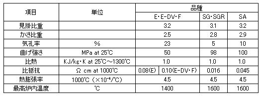
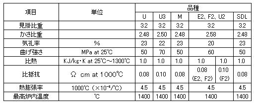
Physical Characteristics
| Characteristics Items | Unit | Type | |||||
|---|---|---|---|---|---|---|---|
| E2 | E2-DV | F2 | SDL2 | SG/SGR | SA | ||
| Apparent Density | 3.2 | 3.2 | 3.2 | 3.2 | 3.1 | 3.2 | |
| Bulk Density | 2.58 | 2.58 | 2.58 | 2.58 | 2.8 | 2.9 | |
| Apparent Porosity | % | 20 | 20 | 20 | 20 | 5 | 10 |
| Bending Strength | MPa at 25℃ | 60 | 60 | 60 | 50 | 98 | 100 |
| Specific Heat | KJ/kg・Kat 25℃ to 1300℃ | 1.0 | 1.0 | 1.0 | 1.0 | 1.0 | 1.0 |
| Specific Resistance | Ωcm at 1000℃ | 0.08 | 0.10 | 0.10 | 0.08/0.10 | 0.016 | 0.045 |
| Coefficient of Thermal Expansion | 1000℃(x10-6/℃) | 4.5 | 4.5 | 4.5 | 4.5 | 4.5 | 4.5 |
| Surface Temperature of Heating Element | ℃ | 1400 | 1400 | 1400 | 1400 | 1600 | 1600 |
| EREMA(R) Heating Elements Dia. | mm | 16 to 30 | 16 to 30 | 35 to 50 | 14 to 50 | 16 to 55 | 16 to 35 |
| Characteristics Items | Unit | Type | |||||||
|---|---|---|---|---|---|---|---|---|---|
| U2 | U3 | M2 | E7/F7/U7 | ||||||
| Apparent Density | 3.2 | 3.2 | 3.2 | 3.2 | |||||
| Bulk Density | 2.58 | 2.50 | 2.58 | 2.65 | |||||
| Apparent Porosity | % | 20 | 22 | 20 | 17 | ||||
| Bending Strength | MPa at 25℃ | 60 | 70 | 60 | 60 | ||||
| Specific Heat | KJ/kg・K at 25℃ to 1300℃ | 1.0 | 1.0 | 1.0 | 1.0 | ||||
| Specific Resistance | Ω cm at 1000℃ | 0.08 | 0.10 | 0.10 | 0.08 | 0.08 | 0.10 | ||
| Coefficient of Thermal Expansion | 1000℃ (x10-6/℃) | 4.5 | 4.5 | 4.5 | 4.5 | ||||
| Surface Temperature of Heating Element | ℃ | 1400 | 1400 | 1400 | 1400 | ||||
| EREMA(R) Heating Elements Dia. | mm | 16 to 30 | 35 to 50 | 16 to 30 | 12 to 30 | 20 to 30 | 35 to 40 | ||
Typical Resistance Temperature
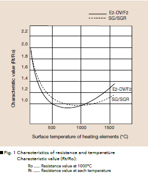
As shown in Fig.1, the temperature coefficient of EREMA resistance-temperature characteristics is negative up to 650℃ to 700℃ (When the temperature goes up, the resistance value goes down). Then, when it exceeds that temperature, it becomes positive (When the temperature goes up, the resistance value goes up.).
Note. The EREMA resistance is usually measured at 1000℃ in open air and the nominal resistance differs extremely from that measured at room temperature. (Refer to Fig. 1)
Chemical Characteristics
The EREMA heating elements are made of chemically stable silicon carbide with high purity and are superior to metal heating elements in terms of high temperature stability, oxidation resistance and corrosion resistance. When the heating elements are operated at high temperatures, they come into contact and react with a gas atmosphere such as vapor, hydrogen, nitrogen, sulfur, halogen, etc., molten alkali, alkaline salts (K2CO3, KCl, KOH, NaF, etc.), molten metals (Fe, Ni, Co, etc.), and some metal oxides (CuO, Pb3O4, FeO, etc.), and will be affected by erosion or oxidation when the above reactions occur.
When EREMA heating elements are handled in a gas atmosphere, refer to
“Effects of Atmosphere Condition on EREMA Heating Elements.” In designing a furnace, when the above corrosive substances by which EREMA is affected are involved, caution must be exercised to avoid any direct contact by EREMA.
LIFE OF EREMA HEATING ELEMENTS
Silicon carbide heating elements are generally subject to gradual oxidation, the formation of Silica and an increase in electric resistance, so called deterioration while in use.
This oxidation reaction is shown in the following formula.
SiC + 2O2 → SiO2 + CO2
Silicon carbide (SiC) reacts with oxygen (O2) in the atmosphere and the surface of the heating elements gradually oxides, forming Silica (SiO2), which is an insulator, while its amount increases. This raises electrical resistance. Oxidation occurs when the temperature reaches 800℃ and is accelerated as the temperature increases. Rapid oxidation will occur in the early stage of use, but the rate of oxidation will gradually diminish.
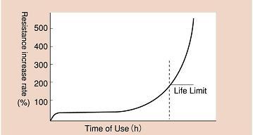
Fig 3 ) Increase in Resistance (Type E2, E-DV2 and F2)
General variation in electrical resistance is shown in Fig. 3. For Types E2, E-DV2, F2, U2 and M2, the service life limit is suggested to be when its resistance increases to about 3 times the initial resistance. (The life of SG and SGR lasts until resistance reaches 1.7 times the original value). The reason is that, reaching an approximate threefold increase, the variation in each element’s resistance becomes greater and heat distribution per one element worsens, causing inefficient temperature distribution in the furnace chamber.
Also, silicon carbide heating elements, when coming to the end of their life, cause not only resistance increase but changes in apparent porosity and fracture damage by deterioration in strength, so caution must be exercised.
Especially Types SG and SGR have a tendency to cause meltdown when approaching the end of their lives.
Caution must be exercised, as the time required for electric resistance to increase three times the initial value i.e. the life of heating elements, varies greatly according to the following application conditions.
It varies depending on (1) Operation Temperature (2) Surface Loading (3) Atmospheres and Materials to be Processed (4) Energizing Method (5) Electrical Connection (6) Installation Method of Heating Elements.
Detailed explanations are given as follows.
Operation Temperature
The higher the temperature of EREMA elements, the shorter the life. Oxidation accelerates and the life shortens especially when the furnace chamber temperature exceeds 1400℃ (for Types E, E-DV, F, U and M) or 1600℃ (for Types SG and SGR). Therefore, it is recommended the surface temperature of EREMA shall be kept as low as possible when in use. Namely, it is necessary to minimize the difference in temperature between inside the furnace chamber and the EREMA elements. This point will be discussed in the next section on surface loading (W/cm2).
Surface Loading (Watts Density)
When a level of electric power applied to EREMA is expressed, it is expressed in terms of the electric power applied per square centimeter of the heating surface. This is called a surface loading density or a surface loading (W/cm2).
The larger the surface loading density (electric power) of EREMA, the higher the surface temperature, but the higher the temperature, the shorter the life of EREMA elements. As shown in Fig. 4 under the same furnace chamber temperature, the surface temperature of heating elements rises in relation to the increase in the surface loading density.
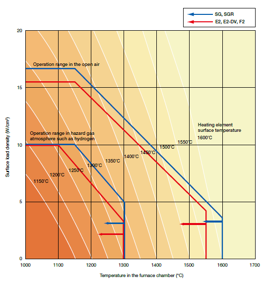
Fig 4 ) Furnace Chamber Temperature, Surface loading (Watts density), and Surface Temperature of Heating Element
Surface Load (Watts Density) Limit
The line of the operation range indicated in Fig. 4 shows the limit of surface load. But practical operation is made with one second to one third of the max. surface load of the limited line.
EREMA Rating
EREMA rating is indicated at the EREMA cold ends. This rated current is the value to keep the temperature of the heating element surface at 1000℃ in open air, and in this case the surface load density will be around 15W/cm2
Caution must be exercised because if this voltage and current is applied to the EREMA element on operation, overloading occurs.
Caution
Thick EREMA heating elements with a diameter of more than f30mm may get thermal shock by the rapid increase in the element temperature, and may fracture and become damaged. When the temperature of the elements starts to increase, it is recommended that the voltage shall be applied from one third the rated voltage and be increased gradually.
Energizing Method (Intermittent and Continuous Operation)
Comparing EREMA element life between the case where it is continuously operated and in the case where it is intermittently operated, it is maximized in the former case. During operation, silicon carbide heating elements oxidize at the surface, where a silica film is formed. With long, continued use this film gradually thickens, resulting in an increase in the resistance of the heating element. The silica film behaves abnormally by expanding or contracting at around the crystal transformation temperature (270℃). If heating elements temperature goes up and down repeatedly around this temperature by intermittent use, the accumulated film will be destroyed repeatedly and oxidation will be promoted. Therefore, when the temperature of the furnace chamber goes down to room temperature due to a power failure etc., the resistance may increase rapidly.
EFFECTS OF ATMOSPHERE CONDITIONS ON EREMA HEATING ELEMENTS
In recent years, cases requiring furnace atmosphere control have been increasing and caution must be exercised for EREMA use in various atmospheres. Similarly, caution is necessary to prevent the reaction of EREMA heating elements with various chemical substances emitted from processed materials during heating operation.
Tokai Konetsu Kogyo has therefore developed special protective coatings (protective films) for special atmosphere or corrosive substances in order to prevent EREMA aging. The correct application of coating increases EREMA’s service life.
In any atmosphere, it is recommended to decrease the surface load as much as possible.
| Atmosphere | Effect | Countermeasure | Recommended coat |
| Vapor | Heater’s lifespan is sometimes cut to less than one fifth of the expected lifespan under dry open-air conditions. | It is important to raise the temperature after purging moisture sufficiently at a low temperature when initiating a new furnace or starting to use one after a long suspension. | U Coat |
|---|---|---|---|
| Hydrogen gas | EREMA’s resistance increases rapidly and its mechanical strength deteriorates quickly if the temperature exceeds 1350℃ in a hydrogen gas atmosphere. The service life, however, depends very much on the intensity of moisture of the gas. | It is recommended that it shall be used at a temperature of less than 1300℃ in the furnace chamber. It is recommended that the surface load shall be decreased as much as possible. (Refer to Fig. 4) | |
| Nitrogen gas | Nitrogen gas reacts with silicon carbide, forming silicon nitride when the temperature exceeds 1400℃, and this shortens the service life. With regard to moisture, it is the same as in the case of hydrogen. | It is recommended that it shall be used at a temperature of less than 1300℃ in the furnace chamber. It is recommended that the surface load shall be decreased as much as possible. (Refer to Fig. 4) | N Coat |
| Ammonia converted gas | This is the same as in the cases of hydrogen gas and nitrogen gas. | It is recommended that it shall be used at a temperature of less than 1300℃ in the furnace chamber. It is recommended that the surface load shall be decreased as much as possible. (Refer to Fig. 4) | N Coat P Coat |
| Decomposition reaction gas | Decomposed hydrocarbon attaches on the surface of EREMA heating elements and may cause short-circuiting in an atmosphere including hydrocarbon. | It is necessary to burn off carbon by occasionally introducing air into the furnace. The electric furnace should be designed with wide spacing between EREMA heating elements to prevent short-circuiting. | |
| Sulfur gas | The surface of heating elements will be damaged and resistance rapidly increases if the temperature of EREMA exceeds 1300℃. | Use the EREMA heating elements under 1300℃. | |
| Vacuum | In the high vacuum, SiO2 protective film is not formed and silicon carbide dissolves itself. As a result, the service life will be shortened. | Avoid operation pressure from getting over 0.13Pa and use it at temperatures below 1100℃. | P Coat |
| Others | Various substances, emitted from processed materials during calcination, including such halides as lead, antimony, alkali and alkaline earth, as well as oxides, chemical compounds thereof may occasionally stick to heating elements and corrode them. | It is important to remove these beforehand from processed materials or exhaust them by installing an exhaust port. | H Coat P Coat, etc. |
* Incorrect coating selection may adversely affect element life. Special coatings are available upon request. Please feel free to contact us.
INSTALLATION OF EREMA HEATING ELEMENTS
1) Handle with care to avoid damage from mechanical shock when installing EREMA heating elements.
2) The standard diameter of a through-hole for an EREMA heating element drilled through the brick layers should be about 1.5 times the diameter of EREMA for the following ranges.
Sizes under f20mm are suitable for brick layers up to 150mm in thickness.
Sizes over f25mm are suitable for brick layers up to 250mm in thickness.
(1) When brick layers are thicker than the above thickness, widen the piercing hole diameter 5mm more.
(2) When SG-type heating element is used, take a 5mm greater margin than the above standard value.
3) EREMA heating elements are electrically conductive.
Care should be taken to avoid electric leakage due to direct contact with a conductive material or electric shock to a human body.
4) It is recommended to use similar electric current ratings in order to equalize EREMA load on the same circuit.
Refer to the initial current rating value marked on the EREMA’s cold end and apply those with close current values on the same circuit.
5) Arrange so that an equal length of both EREMA’s cold ends protrude out of the furnace wall and the heating zone is positioned at the center of the furnace chamber.
6) Install so that EREMA heating elements are positioned at the center of the through-hole of the furnace wall and the surrounding area is filled lightly with ceramic wool as shown in Fig. 5.
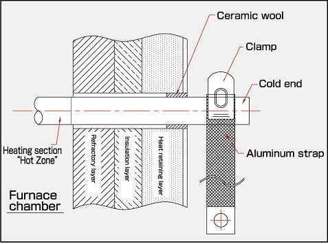
Fig 5 ) EREMA INSTALLATION WITH A TERMINAL CLAMP
7) Make sure that neither the terminal clamp nor the terminal strap will come into contact with the furnace wall directly. Also, the terminal strap must have enough slack to insert a finger.
8) After completing EREMA connections, turn on electricity after lightly pressing the heating element with a finger tip and making sure that it will move easily.
9) When replacing EREMA elements, it is recommended that all heating elements on the same circuit shall be replaced, otherwise the resistance difference between the new and old elements can cause a load difference and could shorten its service life. It is recommended that older or aged EREMA elements shall be used on the same circuit.
10) For safety, it is recommended that installing space shall be given some clearance over the value shown in Fig. 6.
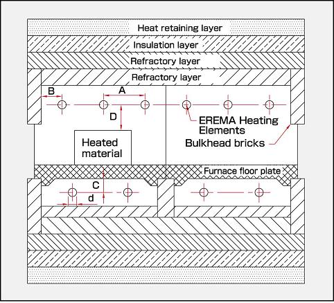
Fig 6 ) Installing space of heating elements
[Recommendable space for heating elements] d: Diameter of heating elements
A: Space of heating element 2d or more
B: Distance from heating element to bulkhead bricks 2d or more (min. 30mm)
C: Distance from heating element to furnace floor plate 2d or more
D: Space from heating element to heated material √2A or more
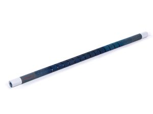
Precautions to Take When Installing EREMA Type SG & SGR
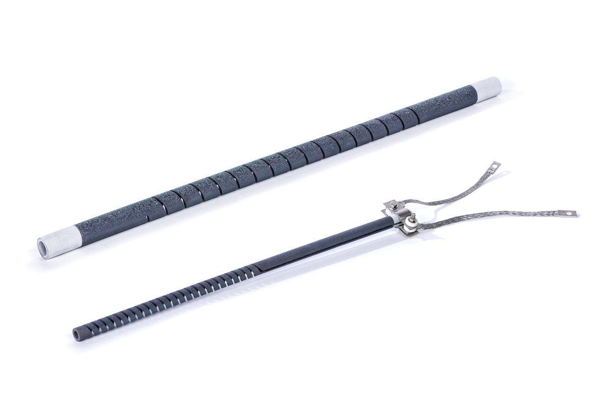
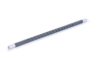
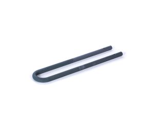
Types SG and SGR have a spirally cut groove, and are consequently vulnerable to mechanical shock. The utmost care must be exercised when handling these types.
1) Unlike other heating elements, Types SG and SGR rotate slightly by expansion or contraction. It is important piercing hole and strap length shall be given some clearance.
2) Furnaces operated at high temperatures should adopt a parallel connection.
3) When installing SGR, fitting a highly pure alumina tube into the through-hole is recommended. (This prevents electrical short-circuiting which may be caused by slipping bricks and the sticking of refractory fragments and help EREMA hold at the center of the through-hole when it is hung from the ceiling.)
When filling up the ceramic wool, wind ceramic wool around the cold end of EREMA before inserting it into the through-hole and then insert the EREMA into the holes.
4) If SGR is to be installed horizontally, adequate support must be provided by not only holding it at the single-end but by drilling a hole through the inner wall of the furnace chamber.
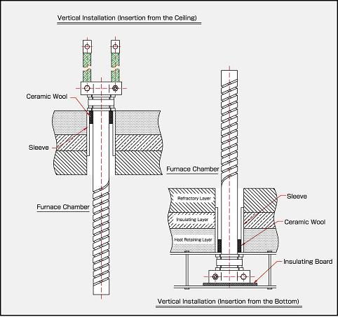
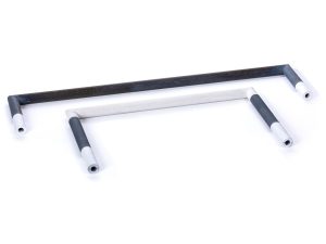
Fig 7 ) Installation of Type SGR
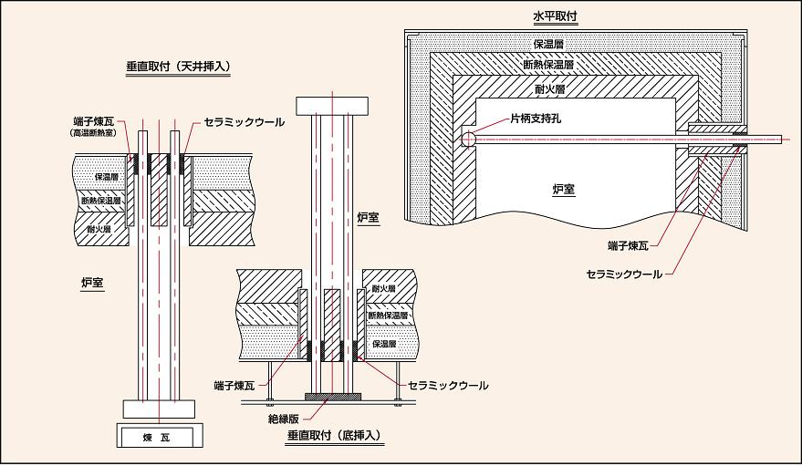
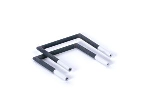
Fig 8 ) Installation of Type U2
Note: A set pin can be used for the U2-type vertical installation (ceiling insertion).
(Selection of pin hole size is option.)
SUGGESTIONS FOR SELECTING EREMA HEATING ELEMENTS
Determination of electric capacity for box type furnace
From heat loss through furnace walls, the electric capacity can be approximated from the following formula and figures.
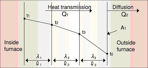
Fig 9 )
The temperature raising time and thermal capacity of processed material are not included in this formula.
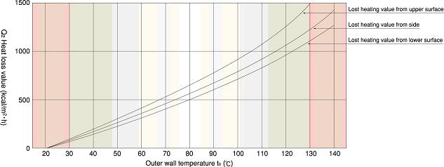
Fig 10 ) Relation between outer wall temperature and heat diffusion amount
Connection
Combination of series and parallel connections are generally used with EREMA heating elements. The maximum number of EREMA heating elements in series must be limited to 2 units, or a two-step series connection must be used. If the furnace chamber temperature exceeds 1350℃, a parallel connection must be used. Open delta connection (single-phase 3 circuits) is recommended for a three-phase connection.
- Single-phase parallel connection (Fig.11)
- Single-phase 2 units series and parallel connections (Fig.12)
- Open delta connection (Fig. 13)
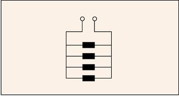
Fig 11 ) Single-phase parallel connection
Fig 12 ) Single-phase 2 units, series connection and parallel connection
Fig 13 ) Open delta connection (single phase 3 circuits)
Calculation of Rated Voltage
The rated voltage can be obtained by the following formula.
Here
V: Circuit rated voltage [V]
Pm: Equipment power [W]
R: Resistance [W] of EREMA at 1000 [℃] (Refer to Specification Table)
S: Numbers of series connection [units]
P: Numbers of parallel connection [units]
(Calculation example)
Equipment power Pm=16 [kw]
2S-8P (2 units series connection, 8 units parallel connections)
If EREMA E16 x 400 x 300 (2.21W) is used:
= 94.0 -> 90[V]
Round down the obtained voltage (94.0V) to (90V) based on 5V as a unit.
Electric Power Control Devices
As described earlier, the resistance of EREMA heating elements increases during operation requiring a voltage compensating device against resistance change. A thyristor control device or multi-tapped transformer will be used for this purpose. As a recent trend, a thyristor power control devices with a matching transformer are most commonly used due to the following advantages:
(1) Long service life because of no moving parts and contact-less control are used.
(2) Accurate temperature control is possible because of its rapid response.
(3) Temperature control is fully automated with easy control of PID (proportion, integration and differentiation) and
program control being readily available.
(4) Compact and weighs less than the conventional power regulators.
(5) It is easy to handle, reliable, and easy to maintain.
Capacity of Power Control Device
The capacity of an EREMA electric furnace is generally indicated by equipment power in kW and the capacity of the transformer and thyristor is indicated by the apparent power of kVA. The capacity of a transformer has a 10% margin.
kVA = 1.1 x Pm
For example, the capacity of a transformer is 33 kVA if the equipment capacity of an electric furnace is 30 kW. The capacity of a thyristor matching transformer is determined in the following way.
kVA = (1.15 to 1.20) x Pm
Extent of Secondary Voltage Compensation
As outlined in the section”Life of EREMA Heating Elements” heating elements should be replaced when the resistance increases to 3 times the initial resistance for Types E2, E2-DV, F2, U2 and M2, and increase by about 1.7 times for Types for Type SG and SGR. Consequently, the extent of compensation is as follows.
Types E2, E2-DV, F2, U2 and M2 1.73 × rated voltage
Types SG and SGR 1.3 × rated voltage
The secondary voltage range for the thyristor matching transformer is voltage compensated with a three to four-step tap.
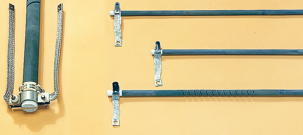
TERMINAL ACCESSORIES OF EREMA HEATING ELEMENTS
Terminal clamps and terminal straps are supplied with EREMA heating elements. Loop the strap uniformly around the EREMA terminal in the circumferential direction, and fasten it evenly using the clamp. For higher temperatures or atmosphere furnaces, heat-proof terminal clamps and straps should be applied because those terminals are exposed to high heat due to the structure of the furnaces.
Type SL Terminal Strap / Type SH Terminal Strap
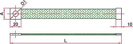
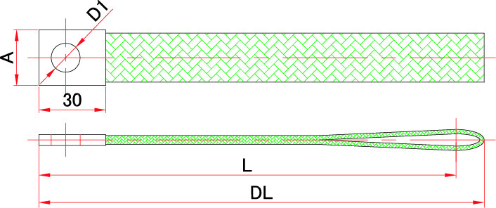
Type SL Terminal Strap / Type SH Terminal Strap
Type SL
Type SH
Standards for Terminal Strap(Unit:mm)
| No. | EREMA Dia.(φ) | L | DL | A | D1 | Rated current value (Unit:A) |
|
|---|---|---|---|---|---|---|---|
| SL-12 | 12 | 150 | 12 | 7 | 30 | ||
| SL-14 | 14 | 20 | 10 | 75 | |||
| SL-16 | 16 | ||||||
| SL-20 | 20 | 180 | |||||
| SL-25 | 25 | 200 | 23 | 100 | |||
| SH-30 | 30 | 250 | 25 | 13 | 300 | ||
| SH-35 | 35 | 300 | 350 | ||||
| SH-40 | 40 | ||||||
| SH-45 | 45 | ||||||
| SH-50 | 50 |
Material : Aluminum
Type HV Terminal Clamps
Type HV Terminal Clamps
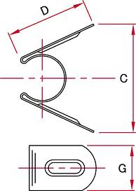
Standards for HV Terminal Clamps (Unit : mm)
| No. | EREMA Dia.(φ) | D | G | C |
|---|---|---|---|---|
| HV-10 | 10 | 28 | 10 | 25 |
| HV-12 | 12 | 30 | 12 | 30 |
| HV-14 | 14 | 35 | 14 | 40 |
| HV-16 | 16 | 16 | ||
| HV-20 | 20 | 40 | 20 | 55 |
| HV-25 | 25 | 50 | 25 | 60 |
| HV-30 | 30 | 60 | 30 | 75 |
| HV-35 | 35 | 65 | 35 | 85 |
| HV-40 | 40 | 70 | 40 | |
| HV-45 | 45 | 80 | 95 | |
| HV-50 | 50 |
Material : SUS304
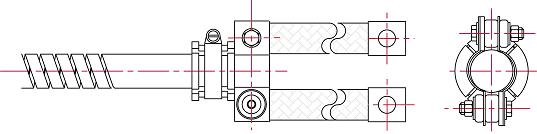
Furnaces Heat-proof Terminal (Clamps and Straps)
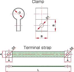
Furnaces Heat-proof Terminal (Clamps and Straps)
Standard for Furnaces Heat-proof Terminals (Unit:mm)
| Clamp | Terminal strap | Clamping Bolt | Strap rated current value (Unit:A) |
|||||||||
|---|---|---|---|---|---|---|---|---|---|---|---|---|
| EREMA Dia. (φ) |
No. | D | B | D1 | No. | L | A | D2 | Screw Dia (φ) |
Length | ||
| 12 | G-12 | 13 | 17 | 7 | GH-12 | 90 | 17 | 7 | 5 | 20 | 150 | |
| 14 | G-14 | 15 | 20 | 10 | GH-14 | 20 | 10 | 8 | 30 | |||
| 16 | G-16 | 17 | 22 | GH-16 | 100 | 22 | ||||||
| 20 | G-20 | 21 | 25 | GH-20 | 120 | 25 | 200 | |||||
| 25 | G-25 | 27 | 30 | GH-25 | 140 | 30 | 35 | 225 | ||||
| 30 | G-30 | 32 | 35 | 13 | GH-30 | 300 | 35 | 13 | 10 | 40 | 300 | |
| 35 | G-35 | 37 | 40 | GH-35 | 40 | 45 | ||||||
| 40 | G-40 | 42 | 45 | GH-40 | 50 | |||||||
| 45 | G-45 | 47 | 50 | GH-45 | ||||||||
| 50 | G-50 | 52 | GH-50 | |||||||||
Material:Clamp···Aluminum, SUS304
Material:Strap···Aluminum
Connecting Terminal for EREMA SGR Type
Connecting Terminal for EREMA SGR Type
Standard Size

* We also accept production of non-standard dimensions.