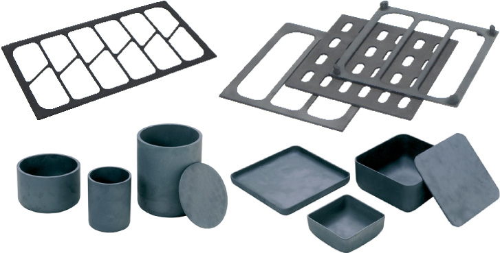


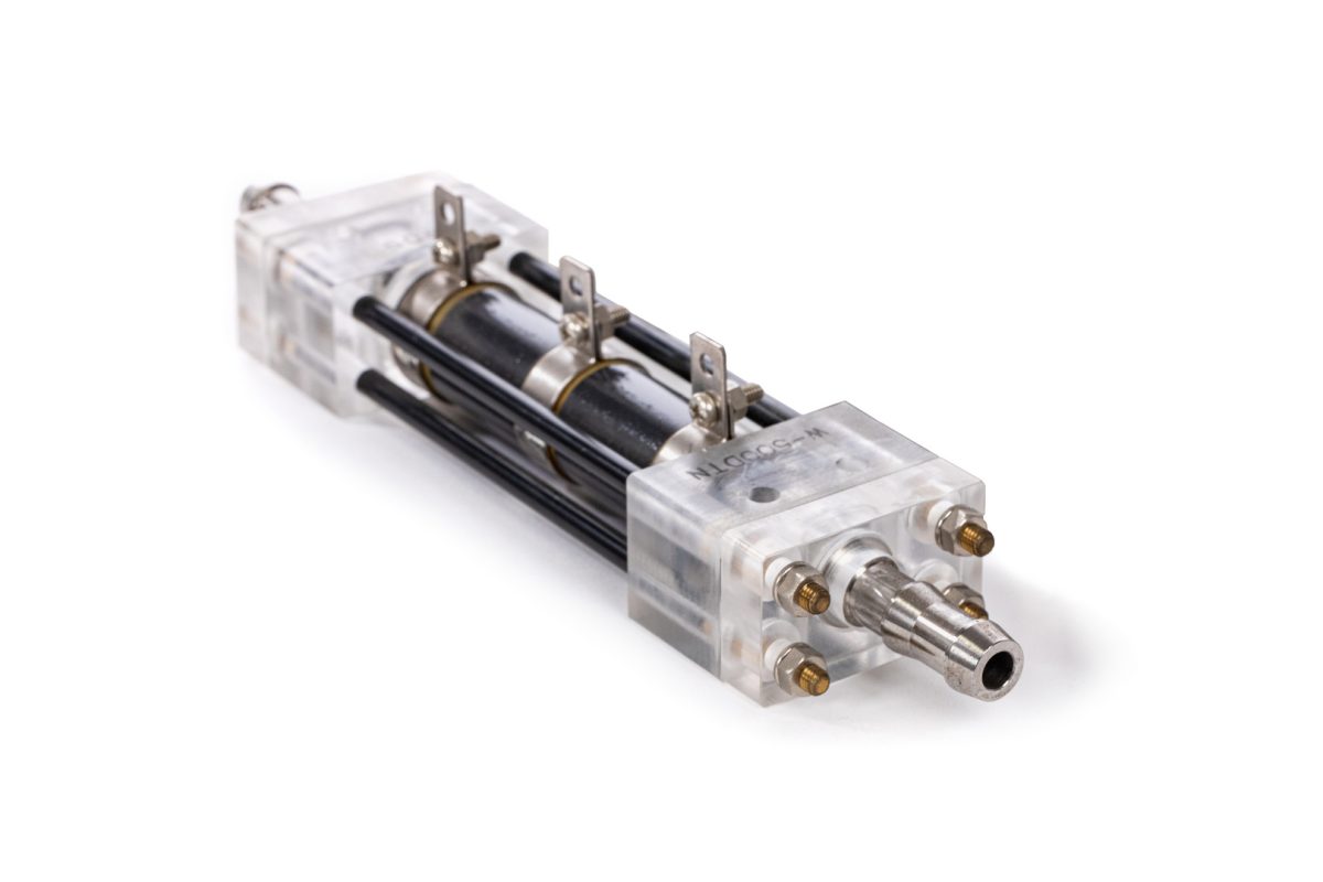
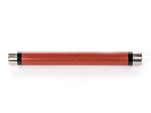
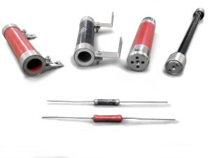
EREMA® (ELECTRIC RESISTANCE MATERIAL)
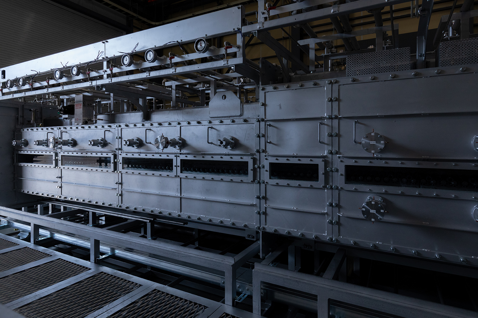
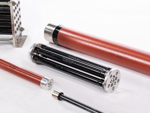
Since 1961, we have been involved in the manufacturing and sale of ceramic resistors, contributing to the improvement of technologies and performance in a wide range of fields including electric power, communications and healthcare. EREMA resistors are ceramic resistors sintered at a high temperature. They are therefore optimal for circuits which must be highly reliable under extreme conditions.

Major Features
- No risk of disconnection and higher reliability
- Higher withstand voltage
- Minimized dimensions but applicable at higher electric power
- Non-induction (BF and BFH excluded)
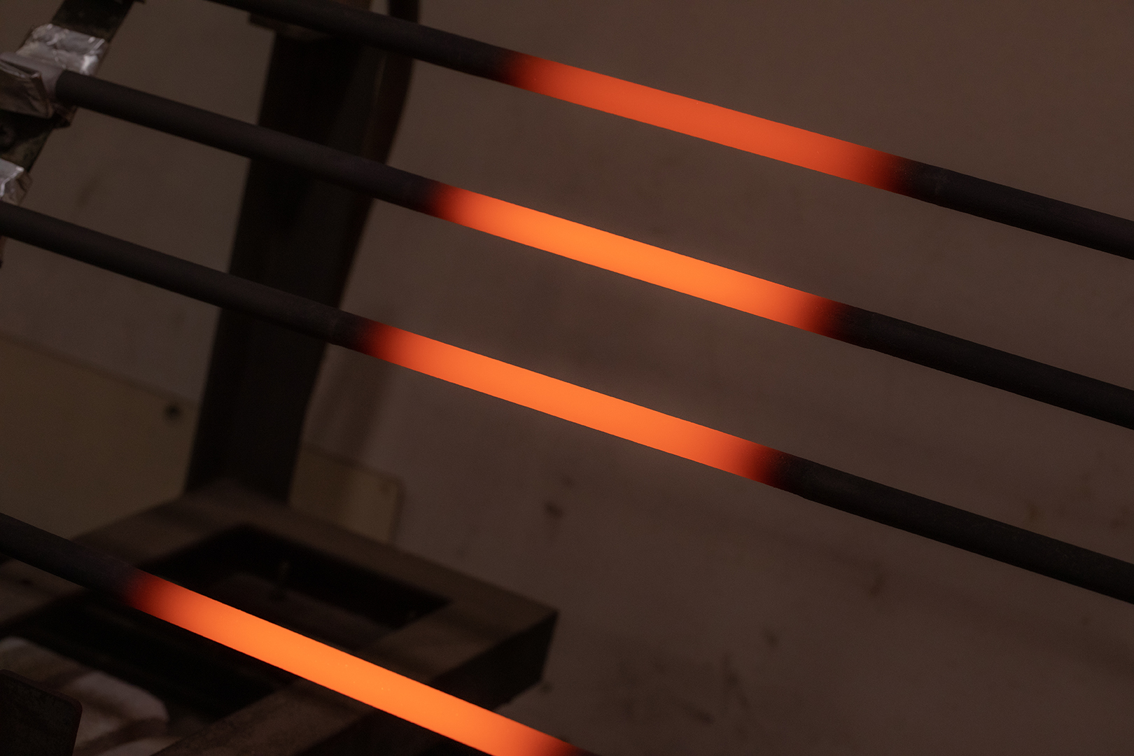
- Operative at higher temperature
- Higher thermal and chemical stability
- Usable in water, vapour and oil
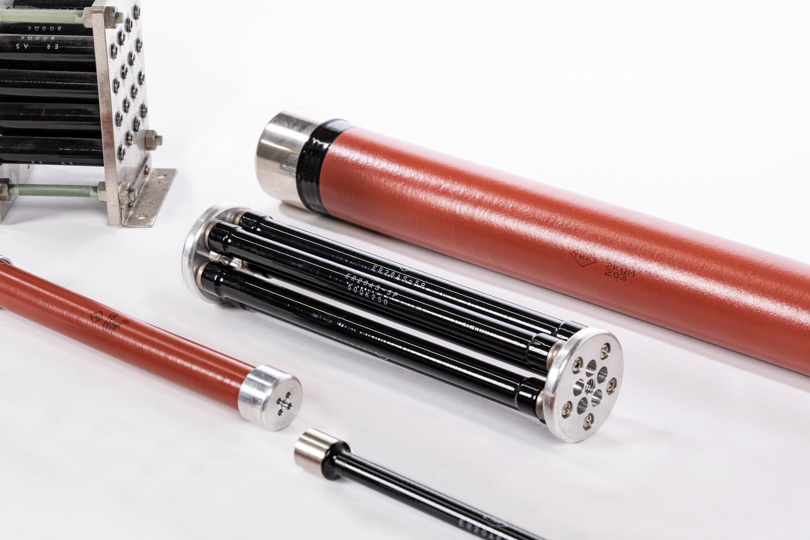
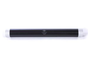
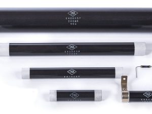
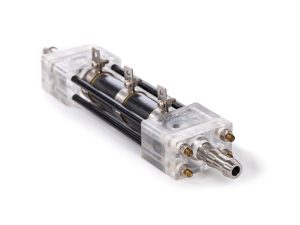
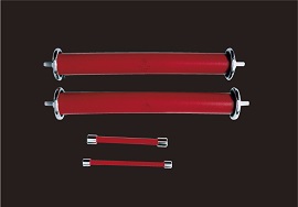
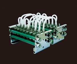
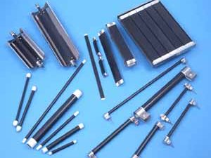
Products
Points to Remember When Using EREMA Resistors
EREMA ceramic resistors, which are widely used for high-voltage and high-power applications, are available in various models with different features. It is important to choose a resistor that fits your application requirements.
1. Points to Remember – Common to EREMA Resistors
To maximize the performance of EREMA ceramic resistors, please follow the instructions below.
1.Overall Attention
(a) Resistors are used under various electrical conditions. Ensure the operational reliability and safety, and perform a trial run as needed before using resistors.
(b) For applications that require high reliability (when using resistors with consumer, medical, power, or nuclear equipment, or an accelerator, for example), contact our sales division to let us know your electrical requirements so that you can use resistors safely.
(c) If resistors are used at an ambient temperature exceeding 40℃, or are exposed to heat radiation by the periphery, reduce the rated power according to the characteristic curve. Generally, we recommend using the resistor at 50% or less of the rated power.
(d) Separate consideration should be given to impulse voltage, transient voltage, intermittent overloading, and pulse loading. Contact our sales division if your application involves applying a high voltage for a short time, intermittent overloading, or pulse loading. Do not design a circuit and determine the power level based only on normal electrical conditions or average power.
(e) Using resistors in an environment with high levels of corrosive gases, dust, humidity, condensation, or salt air, or under other adverse conditions may result in degraded insulation, increased resistance, or corroded terminals. Check the operating environment before use.
(f) The ASH resistors and the C-type terminals for the AS and SP resistors have their terminals secured by lead-free soldering (with a melting point of 217℃). Therefore, make sure that the terminal temperature does not exceed 150℃.
(g) Store resistors at room temperature in a location with low humidity.
(h) When assembling and securing several resistors, use spacers or something similar to ensure that the resistors have the same length to prevent offset loading.
(i) Dropping or bumping EREMA resistors, which are made of ceramic, can result in chips, internal cracks, or breakages, impairing their properties. Therefore, take a special care when handling.
2. Voltage Reduction Ratio with Impulse Waveform
Withstand voltage will change with time constant or wave tail duration on the basis of the standard impulse voltage. Fig.1 represents the withstand voltage reduction ratio versus time when withstand voltage with 1.2/50 µs waveform is defined as 100%. The larger the time constant, or the longer the wave tail duration, the lower the withstand voltage. We recommend considering the voltage reduction ratio and setting a safety factor.
Fig. 1: Voltage Reduction with Impulse Waveform
3. Power Derating with Plural Resistors Combined Together
AS, SP resistors, when used in plural, will exert the influence of radiation heat each other. The reduction ratio shown in Fig.2 is to be noted.